MIL-DTL-83413/8D
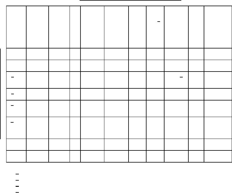
TABLE I. Jumper assembly types and characteristics.
Jumper Construc- Wire and Wire Available
Available Light-
Fuel
Method of
Color
Supersedes
assembly tion type terminal size lug sizes
cable
ning
Compa- attaching
of ID
type
material (see (see tables
tested
band
length,
tible 1/ terminals
table III thru V)
see "L" or
II)
"P"
dimensions
on
figure 1
A
Bonding
Copper
12
A thru J
002-999
No
No
Crimp
No
MS25083-2
band
B
Current
Copper
8
K,L,M,N,T,
002-999
No
No
Crimp
No
MS25083-4
return
U
band
C 2/
Bonding
Aluminum 10 O,P,Q,R,S
003-999
No
Yes
Brazed 4/
Clear
MS25083-1
(aluminum
and -7
only)
D 3/
Quick
Copper
12
A thru G
003-999
No
No
Crimp
No
MS25083-3
disconnect
band
E 3/
Short end Copper
12
A thru G
Fixed
No
No
Crimp
No
MS25083-3S
of quick
length
band
disconnect
F 3/
Long end Copper
12
A thru G
002-999
No
No
Crimp
No
MS25083-3P
of
band
quick
disconnect
G
Bonding Copper
12
A thru J
003-999
Yes
No
Crimp
Yellow
MS25083-5
H
Current
Copper
8
K,L,M,N,T,
003-999
Yes
No
Crimp
Yellow
MS25083-6
return
U
1/
Only fuel compatible jumper assemblies may be used within fuel tank and cells.
2/
Do not use outside fuel tanks and cells.
3/
Inactive for Air Force Airborne use after 9 December 1963.
4/
Dip braze terminals in accordance with AWS-C3.7 Specification for Aluminum
Brazing. A coating is not required on interior strands of the cable, chemical
conversion coating In accordance with MIL-DTL-5541, class 3 shall be applied after
brazing. Inert gas welding using an aluminum based solder or other means of
termination may be used only if approved by the qualifying activity. Aluminum
terminals may be crimped to the cable to facilitate dip brazing. Over crimping shall
be avoided.
2
For Parts Inquires call Parts Hangar, Inc (727) 493-0744
© Copyright 2015 Integrated Publishing, Inc.
A Service Disabled Veteran Owned Small Business